RFID hacking preamble: a new peak detection for the proxmark3
Introduction
Building upon the IIR filter from the last post we’re now going to improve the edge/peak detection fpga module.
Why
The current algorithm is really simple, maybe too simple: whenever the ADC value
is above (resp. below) a hardcoded value, it outputs 1 (resp. 0) with
hysteresis.
There are two problems with that:
- well first, the hardcoded values… For some reason no one has really complained about it so far (?) but you can easily imagine how this could be an issue.
- the module only outputs the peak states (low or high) with an hysteresis using the LOPKD circuit path.
To understand the second point, some details are needed, more easily illustrated
with a captured scope signal (tapping testpoints TP5, which is the raw antenna
signal, and TP1, which is the LOPKD signal, on the proxmark3):
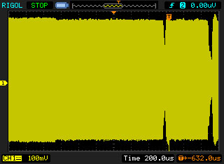
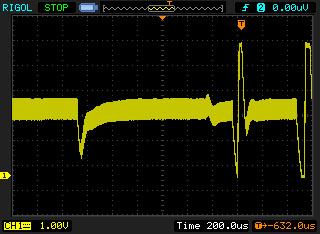
The LOPKD circuit path filters the raw modulated signal and outputs upward (resp.
downward) peaks whenever the signal amplitude increases (resp. decreases). You
also have to remember that with RFIDs, the tag takes its energy from the
magnetic field, and communicates back with the reader, modulating the field
amplitude (consuming more energy on purpose).
Going back to the fpga module, if the signal amplitude is “full”, lo_edge_detect
module outputs 1, and if the signal amplitude is decreased, the module outputs
0. So what’s the problem? Everything sounds fine, doesn’t it?
Well, no… The module forgets one point: when the reader wants to communicate with the tag, it does so by briefly shutting down the magnetic field as seen on the images above. So what happens if the field is modulated “low” by the tag and then the reader needs to send a pulse to the tag, shutting down the field briefly? The LOPKD circuit path properly generates two downward peaks: the first one because the tag decreased the field amplitude and the second one because the amplitude decreased again (down to 0).
This means the lo_edge_detect module properly detects the amplitude state
being low (0), but is not able to detect the 2nd peak as its output is
already 0. This could be an issue if you’re trying to snoop and interpret a
reader-tag communication where this event occurs.
Reinventing the wheel
After trying to work around that limitation using heuristics for a while and obviously failing, living up to our group name, I came to the conclusion a new algorithm couldn’t be avoided anymore.
Detecting peaks is so common, some great algorithm must certainly already exist… So I thought. Unfortunately, there is one major constraint for our implementation: we want to do real-time processing, since we might need to react to whatever signal we’re currently interpreting (acting as a reader or a tag). This means that, any algorithm working with a buffer to process and detect the peaks, or detecting them with a delay won’t work for us. That discarded pretty much any algorithms I could come across (within my very short attention span, thus if you have a good suggestion let me know).
With that constraint in mind, only improving on the thresholding algorithm still seems possible: after all, all we want is to be able to detect two consecutive peaks going in the same direction. Obviously, the new module can’t just output the peak levels, but needs an output which toggles each time a new peak is detected. For backward compatibility reasons, though, the peak levels are being kept as well.
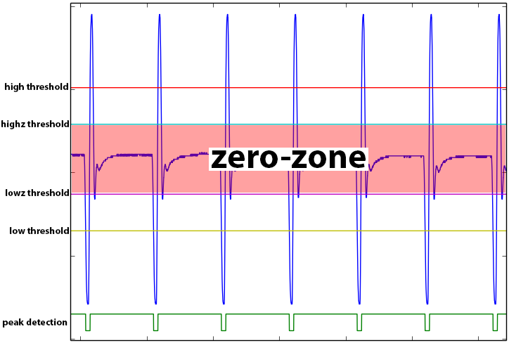
With my blood sugar level low, here is the patent-pending algorithm I could come up with: toggle the output whenever a high (resp. low) threshold is reached, but only if a ‘near-zero’ zone was reached since the last toggle.
always @(posedge clk)
if (enabled) begin
    // To enable detecting two consecutive peaks at the same level
    // (low or high) we check whether or not we went back near 0 in-between.
    // This extra check is necessary to prevent from noise artifacts
    // around the threshold values.
    if (trigger_enabled & (is_high | is_low)) begin
        output_edge <= ~output_edge;
        trigger_enabled <= 0;
    end else
        trigger_enabled <= trigger_enabled | is_zero;
end
In practice, that means having a high and low threshold as well as a high-zero and low-zero threshold.
always @(posedge clk)
begin
    is_high <= (adc_d >= high_threshold);
    is_low <= (adc_d <= low_threshold);
    is_zero <= ((adc_d > lowz_threshold) & (adc_d < highz_threshold));
end
Auto-tuned thresholds
Life looks beautiful and all, except the algorithm went from having two hardcoded thresholds to having 4 of them. Obviously that makes it even more sensitive, and far less robust to different signal amplitudes. Indeed, just moving the antenna is enough to make it fail.
There’s a simple solution to that though: we can auto-tune the threshold values using the maximum and minimum values being reached and some magic rule of thumb formulas.
// auto-tune
wire [7:0] high_threshold = (max + min) / 2 + (max - min) / 4;
wire [7:0] highz_threshold = (max + min) / 2 + (max - min) / 8;
wire [7:0] lowz_threshold = (max + min) / 2 - (max - min) / 8;
wire [7:0] low_threshold = (max + min) / 2 - (max - min) / 4;
Envelope follower
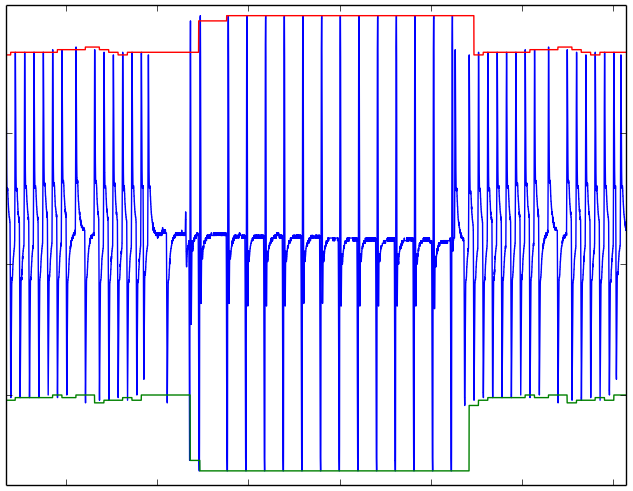
And that’s almost good to go, but take a look at this example:
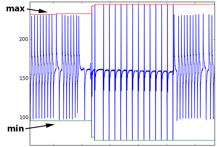
As you can see, we have a burst of higher amplitude peaks in the middle (they are the reader’s pulses, whereas the other ones are the tag’s modulations). Hence, with a naive min max approach, the computed thresholds after this burst could be overly optimistic and miss some smaller peaks (although not in this case insofar as the amplitude difference isn’t too big).
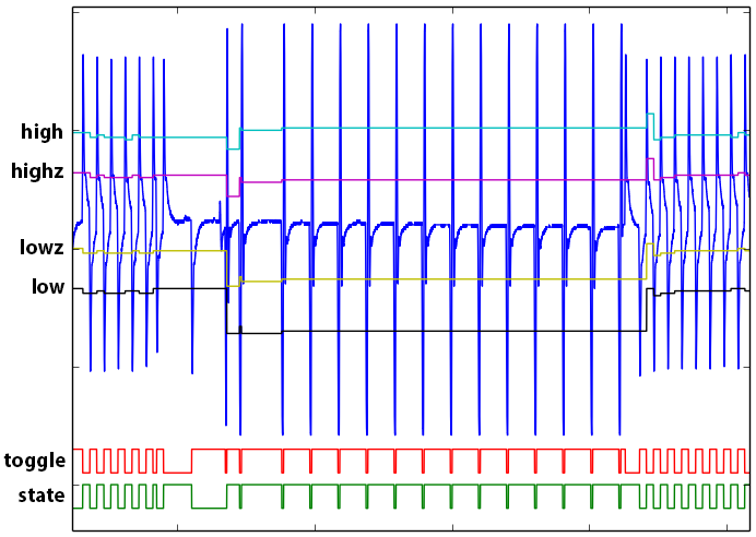
The idea is therefore to come up with some kind of min/max envelope follower which yields the following result:
The idea of this algorithm is fairly simple as well: it just tracks the current minimum (resp. maximum) value since the last maximum (resp. minimum) value/peak. In other words, each time the signal has a peak in the opposite direction, the minimum or maximum value is reset. There is just one small heuristic using a threshold to decide whether or not a minimum/maximum value is peak or just a local fluctuation.
For more details about this envelope follower, you can read the following verilog code:
//-----------------------------------------------------------------------------
// Copyright (C) 2014 iZsh <izsh at fail0verflow.com>
//
// This code is licensed to you under the terms of the GNU GPL, version 2 or,
// at your option, any later version. See the LICENSE.txt file for the text of
// the license.
//-----------------------------------------------------------------------------
// track min and max peak values (envelope follower)
//
// NB: the min value (resp. max value) is updated only when the next high peak
// (resp. low peak) is reached/detected, since you can't know it isn't a
// local minima (resp. maxima) until then.
// This also means the peaks are detected with an unpredictable delay.
// This algorithm therefore can't be used directly for realtime peak detections,
// but it can be used as a simple envelope follower.
module min_max_tracker(input clk, input [7:0] adc_d, input [7:0] threshold,
    output [7:0] min, output [7:0] max);

    reg [7:0] min_val = 255;
    reg [7:0] max_val = 0;
    reg [7:0] cur_min_val = 255;
    reg [7:0] cur_max_val = 0;
    reg [1:0] state = 0;

    always @(posedge clk)
    begin
        case (state)
        0:
            begin
                if (cur_max_val >= ({1'b0, adc_d} + threshold))
                    state <= 2;
                else if (adc_d >= ({1'b0, cur_min_val} + threshold))
                    state <= 1;
                if (cur_max_val <= adc_d)
                    cur_max_val <= adc_d;
                else if (adc_d <= cur_min_val)
                    cur_min_val <= adc_d;
            end
        1:
            begin
                if (cur_max_val <= adc_d)
                    cur_max_val <= adc_d;
                else if (({1'b0, adc_d} + threshold) <= cur_max_val) begin
                    state <= 2;
                    cur_min_val <= adc_d;
                    max_val <= cur_max_val;
                end
            end
        2:
            begin
                if (adc_d <= cur_min_val)
                    cur_min_val <= adc_d;
                else if (adc_d >= ({1'b0, cur_min_val} + threshold)) begin
                    state <= 1;
                    cur_max_val <= adc_d;
                    min_val <= cur_min_val;
                end
            end
        endcase
    end

    assign min = min_val;
    assign max = max_val;

endmodule
Putting it all together
We now have a peak detector with the following features:
- It uses a low-pass IIR filter to clean the signal.
- It can either output the peak levels or toggle its output each time a peak is detected. Hence it can detect consecutive same level peaks unlike before.
- It only relies on one user-set threshold to deem what a peak is, but the value is not as critical as before. The default value is currently set to 127.
- The threshold can be dynamically set from the ARM side using the
FPGA_CMD_SET_EDGE_DETECT_THRESHOLDfpga command. - And finally, it uses an envelope follower to dynamically adjust the peak thresholds.
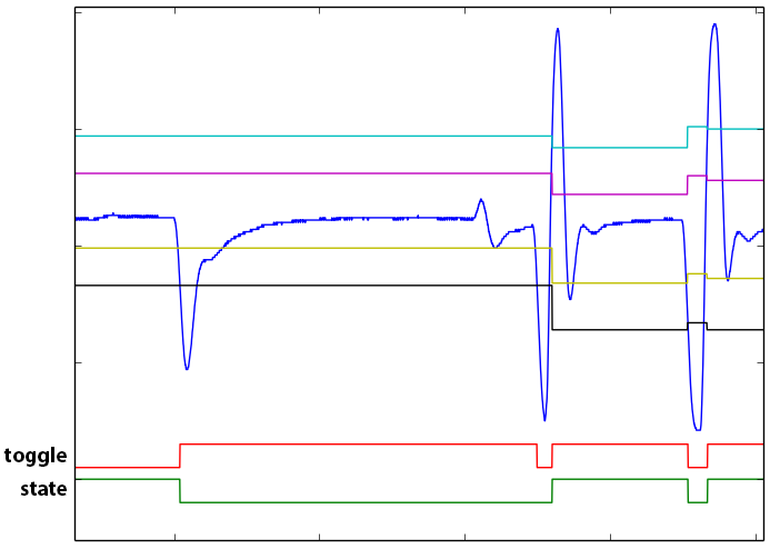
Let’s illustrate this with a final signal, one snooped from a real tag programmer.
Zooming in, you can see how the two consecutive low peaks are properly detected:
Wrapping up
Although not very technical and probably a little bit boring, hopefully this blog post will demystify and encourage people to improve the proxmark3 code, especially the fpga one: adding new DSP features as needed instead of working around and going for the quick and ugly hack :-).
The code has been committed to the proxmark3 repository here, with testbenches and golden tests as well (be nice, and don’t break them? ^^ ).
Finally we have the needed building bricks in place to get our free coffee, so stay tuned for the next post! :-)
As a reference, here are the code for the modules:
//-----------------------------------------------------------------------------
// Copyright (C) 2014 iZsh <izsh at fail0verflow.com>
//
// This code is licensed to you under the terms of the GNU GPL, version 2 or,
// at your option, any later version. See the LICENSE.txt file for the text of
// the license.
//-----------------------------------------------------------------------------
// input clk is 24Mhz
`include "min_max_tracker.v"

module lf_edge_detect(input clk, input [7:0] adc_d, input [7:0] lf_ed_threshold,
    output [7:0] max, output [7:0] min,
    output [7:0] high_threshold, output [7:0] highz_threshold,
    output [7:0] lowz_threshold, output [7:0] low_threshold,
    output edge_state, output edge_toggle);

    min_max_tracker tracker(clk, adc_d, lf_ed_threshold, min, max);

    // auto-tune
    assign high_threshold = (max + min) / 2 + (max - min) / 4;
    assign highz_threshold = (max + min) / 2 + (max - min) / 8;
    assign lowz_threshold = (max + min) / 2 - (max - min) / 8;
    assign low_threshold = (max + min) / 2 - (max - min) / 4;

    // heuristic to see if it makes sense to try to detect an edge
    wire enabled =
        (high_threshold > highz_threshold)
        & (highz_threshold > lowz_threshold)
        & (lowz_threshold > low_threshold)
        & ((high_threshold - highz_threshold) > 8)
        & ((highz_threshold - lowz_threshold) > 16)
        & ((lowz_threshold - low_threshold) > 8);

    // Toggle the output with hysteresis
    // Set to high if the ADC value is above the threshold
    // Set to low if the ADC value is below the threshold
    reg is_high = 0;
    reg is_low = 0;
    reg is_zero = 0;
    reg trigger_enabled = 1;
    reg output_edge = 0;
    reg output_state;

    always @(posedge clk)
    begin
        is_high <= (adc_d >= high_threshold);
        is_low <= (adc_d <= low_threshold);
        is_zero <= ((adc_d > lowz_threshold) & (adc_d < highz_threshold));
    end

    // all edges detection
    always @(posedge clk)
    if (enabled) begin
        // To enable detecting two consecutive peaks at the same level
        // (low or high) we check whether or not we went back near 0 in-between.
        // This extra check is necessary to prevent from noise artifacts
        // around the threshold values.
        if (trigger_enabled & (is_high | is_low)) begin
            output_edge <= ~output_edge;
            trigger_enabled <= 0;
        end else
            trigger_enabled <= trigger_enabled | is_zero;
    end

    // edge states
    always @(posedge clk)
    if (enabled) begin
        if (is_high)
            output_state <= 1'd1;
        else if (is_low)
            output_state <= 1'd0;
    end

    assign edge_state = output_state;
    assign edge_toggle = output_edge;

endmodule
and
//-----------------------------------------------------------------------------
// Copyright (C) 2014 iZsh <izsh at fail0verflow.com>
//
// This code is licensed to you under the terms of the GNU GPL, version 2 or,
// at your option, any later version. See the LICENSE.txt file for the text of
// the license.
//-----------------------------------------------------------------------------
//
// There are two modes:
// - lf_ed_toggle_mode == 0: the output is set low (resp. high) when a low
//   (resp. high) edge/peak is detected, with hysteresis
// - lf_ed_toggle_mode == 1: the output is toggling whenever an edge/peak
//   is detected.
//   That way you can detect two consecutive edges/peaks at the same level (L/H)
//
// Output:
// - ssp_frame (wired to TIOA1 on the arm) for the edge detection/state
// - ssp_clk: cross_lo
`include "lp20khz_1MSa_iir_filter.v"
`include "lf_edge_detect.v"

module lo_edge_detect(
    input pck0, input pck_divclk,
    output pwr_lo, output pwr_hi,
    output pwr_oe1, output pwr_oe2, output pwr_oe3, output pwr_oe4,
    input [7:0] adc_d, output adc_clk,
    output ssp_frame, input ssp_dout, output ssp_clk,
    input cross_lo,
    output dbg,
    input lf_field,
    input lf_ed_toggle_mode, input [7:0] lf_ed_threshold
);

wire tag_modulation = ssp_dout & !lf_field;
wire reader_modulation = !ssp_dout & lf_field & pck_divclk;

// No logic, straight through.
assign pwr_oe1 = 1'b0; // not used in LF mode
assign pwr_oe2 = tag_modulation;
assign pwr_oe3 = tag_modulation;
assign pwr_oe4 = tag_modulation;
assign ssp_clk = cross_lo;
assign pwr_lo = reader_modulation;
assign pwr_hi = 1'b0;

// filter the ADC values
wire data_rdy;
wire [7:0] adc_filtered;
assign adc_clk = pck0;
lp20khz_1MSa_iir_filter adc_filter(pck0, adc_d, data_rdy, adc_filtered);

// detect edges
wire [7:0] high_threshold, highz_threshold, lowz_threshold, low_threshold;
wire [7:0] max, min;
wire edge_state, edge_toggle;
lf_edge_detect lf_ed(pck0, adc_filtered, lf_ed_threshold,
    max, min,
    high_threshold, highz_threshold, lowz_threshold, low_threshold,
    edge_state, edge_toggle);

assign dbg = lf_ed_toggle_mode ? edge_toggle : edge_state;

assign ssp_frame = lf_ed_toggle_mode ? edge_toggle : edge_state;

endmodule