RFID hacking preamble: designing an FPGA IIR filter for the proxmark3
Introduction
At work, they recently replaced the coffee vending machine for a new one. One
detail quickly piqued my interest though: you could now ask the front desk for an
RFID token, pay your coffee with it instead of regular coins, and also deposit
cash into the token at the vending machine.
How does it work? Which RFID IC does it use? Can we play with it? The next
few posts will narrate this journey.
As with any other RFID hacking project, using a proxmark3 is a classic. But, while investigating the vending machine’s low frequency (LF) RFID token, the current proxmark3 LF FPGA code quickly showed its limitations and a need for some serious code overhaul.
Although the following code was implemented only after the hack was successful, it makes more sense to present it first. The hack itself will therefore be explained in later posts.
Proxmark3’s LF FPGA code shortcomings: a glimpse
For anyone who worked with the proxmark3, and ever more so for anyone who added
features, it’s really hard not to have a love-hate relationship with it.
You love the fact that you have the power to hack almost any RFID you can encounter,
but its crude software implementation (and sometimes hardware), to say the least
and not to sound too harsh, is bound to drive you nuts. It’s a shame because this
severely deters from implementing any new features or improvements unless
you’re willing to put some serious energy into it (unless of course you’re into
the quick-and-dirty-code-meh-dont-care category). Yeah yeah [/rant] ;-)
There currently are 3 LF FPGA modules in the proxmark3:
lo_readdrives the antenna’s field, samples and streams the ADC values back to the ARM cpulo_passthruenables bit banging the antenna’s field from the ARMlo_edge_detectcan actively drive the antenna’s field or passively snoop it, and outputs peak/edge states
While hacking the vending machine’s RFID tag, improvements of, or rewriting some of these modules were necessary:
lo_readis actively driving the antenna’s field and you can’t turn it off. This means you can’t get raw ADC values while snooping on an unknown RFID reader-tag communication. You can of course use a real scope, tapping the testpointTP1on the proxmark3’s pcb, but that seriously limits stealthy unknown communication/transaction recordings in environments where discretion would be deemed (unless you feel like dressing as a maintainance guy, and that only works if no one else knows you ;-) ).- You can trace the intent of the original
lo_edge_detectback to 2009 (!) from this forum post. It was fully reimplemented in 2012 by roel. Although the forum post called for configurable thresholds, surprisingly the “algorithm” for the edge detection is quite basic: just two hardcoded thresholds, and the output is either LOW or HIGH when those thresholds are met. There is no way to change those values without recompiling the FPGA code, and needless to say you therefore can’t dynamically compute the thresholds on the ARM side.
A need for filtering
The next blog post will dig into the details of rewriting the lo_edge_detect
module to overcome those limitations and some others but as described from the
forum post, there is one
really annoying thing with the current design: the carrier signal is spilling all
over the places, making it very hard to implement any kind of robust edge detection.
An image is worth a thousand words:
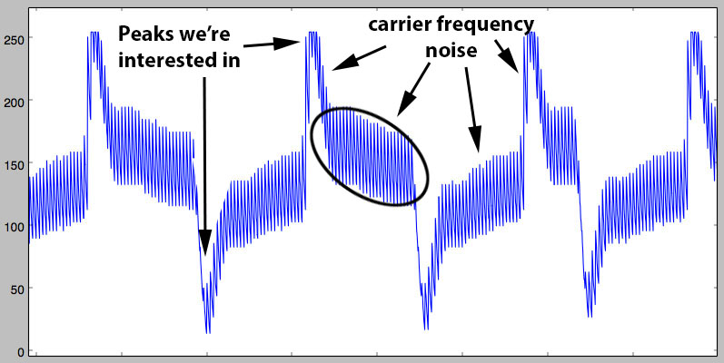
Now, that is some ugly ass signal, isn’t it?!
As you can see, the amplitude of the carrier “noise” is rather large comparing to the peaks, and remembering that the proxmark3’s ADC is only 8bit, you can easily foresee how annoying it is to work with a signal like that.
Indeed, my first rewrite of the lo_edge_detect implementation was very sensitive to
the threshold values, preventing from actually using it in the field, for an
automatic reader-tag communication decoder, without extensive threshold tuning,
which is of course not possible if you don’t want to raise eyebrows.
That was worked around, snooping raw ADC values (after some code
modifications to the lo_read module) and manually decoding the transactions,
yielding to the full pwning of the vending machine, but this monkey work gave
a sour taste.
Let’s therefore sanitize this signal with a low-pass filter to enable for a more robust algorithm…
Smooth like butter
Knowing jack squat about DSP filtering, I got some useful advices from sdjakl, a fellow fail0verflow member: I was told I should look into Butterworth IIR filters, mkfilter and I was provided with a python script to play around and evaluate the response quality of the filter. It’s in situations like this I feel blessed to work with people whose the knowledge sum covers pretty much any field/question, each member having his own very particular set of skills.
IIR filters uses a feedback topology (using multiple input values and multiple past output values) and can use very little memory and resources which makes them a good choice for an FPGA implementation, especially the proxmark3’s tiny one. With mkfilter, given a filter type, the filter’s order (we’ll go with 2), the input sample rate and the cut-off/corner frequency, you get a bunch of information.
The most useful ones for our application being the recurrence relation (what you actually need to implement) and the magnitude vs. frequency graph (to check the actual response of the filter).
On the proxmark3, the main clock is clocked at 24Mhz, the ADC can sample up to 40MS/s hence running at 24Mhz is fine, and the signal we want to filter has useful info up to approx. 40khz and we definitely want to get rid of the carrier noise above 125khz.
Playing around with mkfilter shows that a 20khz corner frequency should
give us a nice filter:
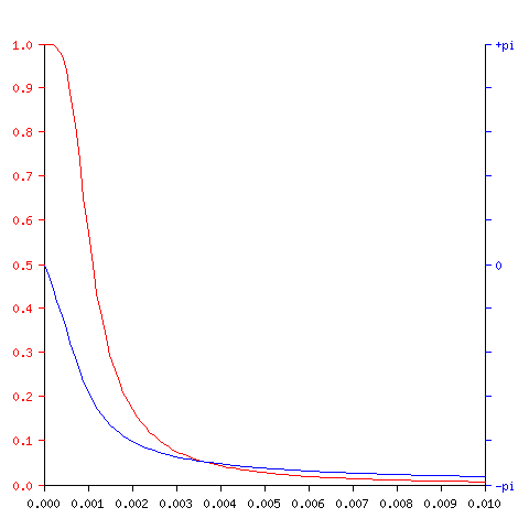
with the following recurrence relation:
y[n] = (  1 * x[n- 2])
     + (  2 * x[n- 1])
     + (  1 * x[n- 0])

     + ( -0.9926225431 * y[n- 2])
     + (  1.9925952288 * y[n- 1])
x[n] being the input samples and y[n] the output values.
As you can see, at 24khz (0.001 of the input frequency) we get 70-80% of the input signal’s amplitude.
Capturing a real signal using my beloved cheap (but noisy!) Rigol’s DS1052e, and running it through a python implementation of the filter:
#!/usr/bin/env python
import numpy
import matplotlib.pyplot as plt

# simulate the proxmark3's ADC 8bit sampling
# ADC's bottom vref is 0.188*VDD = 943mV
# ADC's top vref is 0.811*VDD = 4.055V
def adc_convert(x):
    if x <= 0.943:
        return 0
    if x >= 4.055:
        return 255
    return int((x - 0.943) / ((4.055 - 0.943) / 256))

nx = numpy.fromfile('sig_20MSa_time.bin')
na = numpy.fromfile('sig_20MSa_data.bin')

na = map(adc_convert, na)

td = (nx[1] - nx[0])
print("freq: %f" % (1/td))

def calc_freq(dat, td):
    fftbins = numpy.fft.rfftfreq(len(dat), td)
    fft_d = numpy.fft.rfft(dat)
    mag = numpy.absolute(fft_d)
    return fftbins, mag

def plot_fft(dat):
    fftbins,mag = calc_freq(dat, td)
    # Remove 0-frequency bin as it dwarfs all others
    mag[0] = 0
    plt.plot(fftbins, mag)

def plot_time(dat):
    plt.plot(nx, dat)

def eval_iir(impulse, gain,a,b):
    ll = []
    xv = [0,0,0]
    yv = [0,0,0]
    for e in impulse:
            xv[0] = xv[1]
            xv[1] = xv[2]
            xv[2] = float(e)/gain
            yv[0] = yv[1]
            yv[1] = yv[2]
            yv[2] = (a[0] * xv[0] + a[1] * xv[1] + a[2] * xv[2]
                + b[0] * yv[0] + b[1] * yv[1])
            ll.append(yv[2])
    return ll

impulse = [0,1,0] + [0] * 1000

# 20khz no gain
lf = eval_iir(impulse, 1.0, [1,2,1], [-0.9926225431, 1.9925952288])
ll = eval_iir(na, 1.0, [1,2,1], [-0.9926225431, 1.9925952288])

print max(ll)
print min(ll)

plot_time(ll)

plt.show()
we get the following signal:
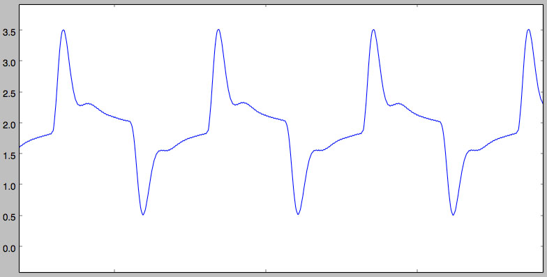
Pretty O:-)
Like a knife through butter
Or is it?
Not quite…
You should have noticed the use of float numbers in the above implementation. While this is a no brainer for a python version, needless to say the proxmark3’s FPGA would not really like it very much, neither would we if we have to implement floating arithmetics.
The idea is therefore to replace those floating numbers with chosen rational numbers which enable replacing costly multiplications with shifts and adds. We could for instance replace -0.9926225431 with -254⁄256 = -0xfe/0x100 = -0.9921875, and 1.9925952288 with 510⁄256 = 0x1fe/0x100 = 1.9921875.
The only problem is that it doesn’t work (mainly because b[1] becomes b[0] + 2). Trying to replace b[1] with 0x1ff/0x100 or 0x1fd/0x100 doesn’t work either. After fiddling around for a bit, you quickly come to the conclusion that, in this case, b[0] and b[1] are so close to each other any rational approximation kills the subtle relationship between them. Changing the corner frequency doesn’t seem to make that much difference either.
The salvation comes when noticing the b coefficients difference increases when decreasing the input sample rate, yielding eventually to the following filter candidate using a 1M samples/sec input sample rate and still the same 20khz corner frequency:
Recurrence relation:
y[n] = (  1 * x[n- 2])
     + (  2 * x[n- 1])
     + (  1 * x[n- 0])

     + ( -0.8371816513 * y[n- 2])
     + (  1.8226949252 * y[n- 1])
Approximating -0.8371816513 with -0xd6/0x100 = -0.8359375 and 1.8226949252 with 0x1d3/0x100 = 1.82421875, simulating the filter and reducing the output values to 8bit (for backward compatibility with the current fpga/ARM code) give us:
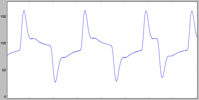
Not quite as pretty, but still much better than the initial signal!
Shifts and ADDs
I won’t insult your intelligence explaining how to replace muls with shifts and adds, but I’ll just point out that since we’re always going to divide by 0x100 (i.e. shift 8 bits right, therefore dropping the bottom 8 bits) we can simplify the shifts and adds to compute the final 8 bits shift on the fly.
For instance, with 0x1d3/0x100:
// 0x1d3 == 0b111010011
// so this is equivalent to
// ((x << 0) + (x << 1) + (x << 4) + (x << 6) + (x << 7) + (x << 8)) >> 8
// which is also equivalent to
// (x >> 8) + (x >> 7) + (x >> 4) + (x >> 2) + (x >> 1) + (x >> 0)
Verilog implementation
The only thing left is the actual HDL implementation which is quite straightforward with verilog. You’ll find it at the end of this post with its testbench as well, or in the proxmark3’s repository.
But of course, it’s never that simple, Murphy always makes sure of that.
With that many 17bit adders and a tiny-ass fpga such as the one used for
the proxmark3 (only 864 LUTs!), the new code exhausted the resources. After
a few days, the love turning to hate, and tired of making the code fugly
for area optimization, it was time for Plan B: the HF and LF fpga code have
been split into two bitstreams and the proxmark3 is now reconfiguring the fpga
on the fly when executing commands. That code was
committed
yesterday, and you’ll need to update your bootrom as well for this change
(since the osimage’s address entrypoint had to be changed to make room for
the two FPGA bitstreams).
What’s next?
Before moving to the actual vending machine hack, and building from this IIR
filter, the next blog post will cover a new lo_edge_detect implementation
providing necessary features for the hack.
Hopefully you found this post useful, and if you have any questions or comments, well, just use the comment box :-)
To be continued…
//-----------------------------------------------------------------------------
// Copyright (C) 2014 iZsh <izsh at fail0verflow.com>
//
// This code is licensed to you under the terms of the GNU GPL, version 2 or,
// at your option, any later version. See the LICENSE.txt file for the text of
// the license.
//-----------------------------------------------------------------------------
// Butterworth low pass IIR filter
// input: 8bit ADC signal, 1MS/s
// output: 8bit value, Fc=20khz
//
// coef: (using http://www-users.cs.york.ac.uk/~fisher/mkfilter/trad.html)
// Recurrence relation:
// y[n] = (  1 * x[n- 2])
//      + (  2 * x[n- 1])
//      + (  1 * x[n- 0])

//      + ( -0.8371816513 * y[n- 2])
//      + (  1.8226949252 * y[n- 1])
//
// therefore:
// a = [1,2,1]
// b = [-0.8371816513, 1.8226949252]
// b is approximated to b = [-0xd6/0x100, 0x1d3 / 0x100] (for optimization)
// gain = 2.761139367e2
module lp20khz_1MSa_iir_filter(input clk, input [7:0] adc_d, output rdy, output [7:0] out);

    // clk is 24Mhz, the IIR filter is designed for 1MS/s
    // hence we need to divide it by 24
    // using a shift register takes less area than a counter
    reg [23:0] cnt = 1;
    assign rdy = cnt[0];
    always @(posedge clk)
        cnt <= {cnt[22:0], cnt[23]};

    reg [7:0] x0 = 0;
    reg [7:0] x1 = 0;
    reg [16:0] y0 = 0;
    reg [16:0] y1 = 0;

    always @(posedge clk)
        if (rdy)
        begin
            x0 <= x1;
            x1 <= adc_d;
            y0 <= y1;
            y1 <=
                // center the signal:
                // input range is [0; 255]
                // We want "128" to be at the center of the 17bit register
                // (128+z)*gain = 17bit center
                // z = (1<<16)/gain - 128 = 109
                // We could use 9bit x registers for that, but that would be
                // a waste, let's just add the constant during the computation
                // (x0+109) + 2*(x1+109) + (x2+109) = x0 + 2*x1 + x2 + 436
                x0 + {x1, 1'b0} + adc_d + 436
                // we want "- y0 * 0xd6 / 0x100" using only shift and add
                // 0xd6 == 0b11010110
                // so *0xd6/0x100 is equivalent to
                // ((x << 1) + (x << 2) + (x << 4) + (x << 6) + (x << 7)) >> 8
                // which is also equivalent to
                // (x >> 7) + (x >> 6) + (x >> 4) + (x >> 2) + (x >> 1)
                - ((y0 >> 7) + (y0 >> 6) + (y0 >> 4) + (y0 >> 2) + (y0 >> 1)) // - y0 * 0xd6 / 0x100
                // we want "+ y1 * 0x1d3 / 0x100"
                // 0x1d3 == 0b111010011
                // so this is equivalent to
                // ((x << 0) + (x << 1) + (x << 4) + (x << 6) + (x << 7) + (x << 8)) >> 8
                // which is also equivalent to
                // (x >> 8) + (x >> 7) + (x >> 4) + (x >> 2) + (x >> 1) + (x >> 0)
                + ((y1 >> 8) + (y1 >> 7) + (y1 >> 4) + (y1 >> 2) + (y1 >> 1) + y1);
        end

    // output: reduce to 8bit
    assign out = y1[16:9];

endmodule
with the following testbench:
//-----------------------------------------------------------------------------
// Copyright (C) 2014 iZsh <izsh at fail0verflow.com>
//
// This code is licensed to you under the terms of the GNU GPL, version 2 or,
// at your option, any later version. See the LICENSE.txt file for the text of
// the license.
//-----------------------------------------------------------------------------
// testbench for lp20khz_1MSa_iir_filter
`include "lp20khz_1MSa_iir_filter.v"

module lp20khz_1MSa_iir_filter_tb;

    integer fin, fout, r;

    reg clk;
    reg [7:0] adc_d;
    wire data_rdy;
    wire [7:0] adc_filtered;

    initial
    begin
        clk = 0;
        fin = $fopen("pcf1w_1MSa_data.in", "r");
        fout = $fopen("pcf1w_1MSa_data.filtered", "w+");
        if (!$feof(fin))
            adc_d = $fgetc(fin); // read the first value
    end

    always
        # 1 clk = !clk;

    always @(posedge clk)
        if (data_rdy) begin
            if ($time > 1)
                r = $fputc(adc_filtered, fout);
            if (!$feof(fin))
                adc_d <= $fgetc(fin);
            else begin
                $fclose(fin);
                $fclose(fout);
                $finish;
            end
        end

    // module to test
    lp20khz_1MSa_iir_filter filter(clk, adc_d, data_rdy, adc_filtered);

endmodule